Raspberry Pi是什么?
引用维基百科的一句话:
The Raspberry Pi is a credit card sized single-board computer developed in the UK by the Raspberry Pi Foundation with the intention of stimulating the teaching of basic computer science in schools.
简单地说,它就是一个基于ARM CPU的、信用卡那么大的迷你计算机。
In short, Pi is an ARM-based mini computer which has a credit card size.
在阅读本文之前,请确保你已经阅读过我的另外几篇关于Pi的文章,因为本文与它们有或多或少的关系。
Before reading this article, please make sure that you've read some other articles of mine on Pi, because this article is more or less based on them.
【1】实验目的 / Experiment purpose
在树莓派上编写一个C程序,通过其GPIO口控制步进电机的转动方向以及速度。
Write a C program to control the direction & speed of rotation of a stepper motor through the GPIO on Raspberry Pi.
【2】为什么要用树莓派来控制步进电机 / Why doing this
在我的概念中,无论是控制接在树莓派上的摄像头来拍照,还是通过树莓派控制LED发光,我都还是在“虚拟世界”中折腾树莓派,因为它没有向外界输出任何动作。而在构建一个稍微复杂的系统时,这种能力可能是很重要的,于是,用树莓派来控制步进电机是我必须要做的事情。
In my view, no matter using Pi to control webcam, or using Pi to light LED, the Raspberry Pi was in a "virtual" world all the time because it didn't output any movement to the real world. Having this ability may be very important to build a slightly more complex system, so I decided to use Pi to control a stepper motor.
文章来源:http://www.codelast.com/
【3】实现方案 / The implementation
怎样通过Raspberry Pi的GPIO口来控制步进电机?已经有很多人这样做了。
How to control a stepper motor through the GPIO on Pi? Lots of people have tried that before.
由于步进电机通常需要一块驱动板,而这样的产品已经很容易买到并且极其廉价(肯定比你自己做要便宜),因此,我们没有必要自己去做。我在淘宝上不断地查啊查,终于找到了白菜价的步进电机和配套驱动板,加起来才一共8块多钱。
Because we need a driver circuit board to drive the stepper motor, and it's really easy to buy this kind of product with super low price nowadays, so it's no need to make it ourselves. I searched taobao.com(the largest e-commerce website in China) and found a super cheap stepper motor & it's matched driver board, they cost me only about 8 RMB, that is, less than $1.5!
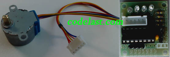
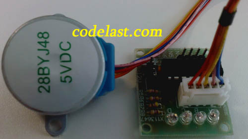
下面来看看我买的步进电机和驱动板的样子:
The stepper motor & it's driver board:
文章来源:http://www.codelast.com/
步进电机和驱动板的接线:
Connect the stepper motor with it's driver board:
文章来源:http://www.codelast.com/
该驱动板配有一个原理图,根据它我们可以知道如何把整个系统连接起来:
The driver board has a schematic diagram and we can learn from it how to connect the whole system together:
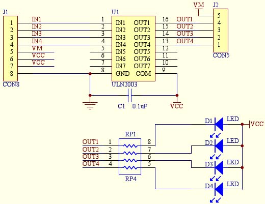
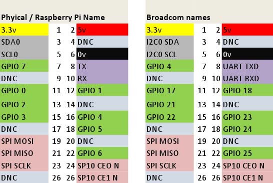
可见,驱动板上有4个输入口:IN1~IN4,这4个口用来接树莓派的4个GPIO口。同时,我们需要为驱动板提供5V的供电,这从哪里来?当然是从树莓派引出来。从下面的GPIO口分布图可以得知,“2”口就是+5V,正好就利用它。
We can see that there are total 4 input pins: IN1~IN4, these 4 pins will be connected to 4 GPIO pins on Raspberry Pi. And we also need to provide a 5V power supply to the board, so where can we get this? Use the pin "2"(5V) next to pin "1"(3.3V) on Pi is the most convenient way. Refer to following GPIO pinouts for details:
文章来源:http://www.codelast.com/
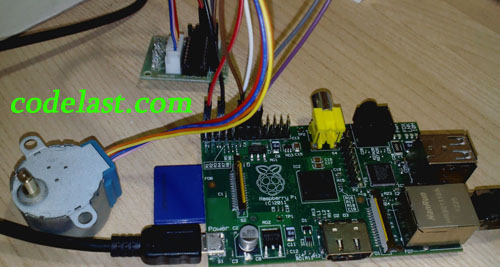
我将树莓派上的GPIO 17、18、21、22口(用树莓派的命名方式就是0、1、2、3口)分别接到步进电机驱动板上的IN1、IN2、IN3、IN4口,最后接好线的效果如下:
I connected GPIO 17, 18, 21, 22(namely GPIO 0, 1, 2, 3 in Raspberry Pi name) on Pi to IN1, IN2, IN3, IN4 on the driver board separately, after it's done, the whole system looks like this:
文章来源:http://www.codelast.com/
【4】编写程序 / Write the program
在参考了这款步进电机配套的51单片机的示例代码后,我知道了依次把驱动板的IN1~IN4置为高电平,就可以驱动步进电机,也就是说,要把树莓派的4个GPIO输出口依次置为高电平。例如,假设用0代表低电平,1代表高电平的话,GPIO 17、18、21、22口的电平第一次被置为1、0、0、0,第二次被置为0、1、0、0,第三次被置为0、0、1、0,第四次被置为0、0、0、1。
After checking the code(for MCS51 singlechip) provided by the product dealer I knew that it's possible to drive the motor by set IN1~IN4 high level in turn, namely set the 4 GPIO pins high level in turn. For example, if we use 0 to represent low level and 1 to represent high level, then GPIO 17, 18, 21, 22 on Raspberry Pi will be set to 1,0,0,0 in the 1st round, 0,1,0,0 in the 2nd round, 0,0,1,0 in the 3rd round and 0,0,0,1 in the 4th round.
于是我写出了下面的代码(仍然使用WiringPi这个库来操作GPIO):
So I wrote the following code(still use WiringPi to manipulate the GPIO):
/* moto.c
* A program to control a stepper motor through the GPIO on Raspberry Pi.
*
* Author: Darran Zhang (http://www.codelast.com)
*/

#include <wiringPi.h>
#include <stdio.h>
#include <unistd.h>
#include <stdlib.h>

#define CLOCKWISE 1
#define COUNTER_CLOCKWISE 2

void delayMS(int x);
void rotate(int* pins, int direction);

int main(int argc,char* argv[]) {
	if (argc < 4) {
		printf("Usage example: ./motor 0 1 2 3 \n");
		return 1;
	}

	/* number of the pins which connected to the stepper motor driver board */
	int pinA = atoi(argv[1]);
	int pinB = atoi(argv[2]);
	int pinC = atoi(argv[3]);
	int pinD = atoi(argv[4]);

	int pins[4] = {pinA, pinB, pinC, pinD};

	if (-1 == wiringPiSetup()) {
		printf("Setup wiringPi failed!");
		return 1;
	}

	/* set mode to output */
	pinMode(pinA, OUTPUT);
	pinMode(pinB, OUTPUT);
	pinMode(pinC, OUTPUT);
	pinMode(pinD, OUTPUT);

	delayMS(50);		// wait for a stable status
	for (int i = 0; i < 500; i++) {
		rotate(pins, CLOCKWISE);
	}

	return 0;
}

/* Suspend execution for x milliseconds intervals.
 *	@param ms Milliseconds to sleep.
 */
void delayMS(int x) {
	usleep(x * 1000);
}

/* Rotate the motor.
 *	@param pins			A pointer which points to the pins number array.
 *  @param direction	CLOCKWISE for clockwise rotation, COUNTER_CLOCKWISE for counter clockwise rotation.
 */
void rotate(int* pins, int direction) {
	for (int i = 0; i < 4; i++) {
		if (CLOCKWISE == direction) {
			for (int j = 0; j < 4; j++) {
				if (j == i) {
					digitalWrite(pins[3 - j], 1); // output a high level
				} else {
					digitalWrite(pins[3 - j], 0); // output a low level
				}
			}
		} else if (COUNTER_CLOCKWISE == direction) {
			for (int j = 0; j < 4; j++) {
				if (j == i) {
					digitalWrite(pins[j], 1); // output a high level
				} else {
					digitalWrite(pins[j], 0); // output a low level
				}
			}
		}
		delayMS(4);
	}
}
文章来源:http://www.codelast.com/
编译程序:
Compile the code:
g++ motor.c -o motor -lwiringPi
运行程序:
Run the program:
./motor 0 1 2 3
这里向程序传入了4个参数,它们分别代表要控制的树莓派的GPIO口。切记,由于使用了WiringPi库,所以要参考上面的GPIO分布图的左边那部分来确定这些数字。
The four arguments passed to the program are the GPIO pin numbers on Pi. Be sure to keep in mind that because of using WiringPi, we need to refer to the left part of the GPIO pinouts image describe above to identify the numbers.
可以看到步进电机已经转动了(如下面的Youku视频所示)。如果你发现转动方向(顺/逆时针)反了,你可以把传入的参数顺序调整一下,就可以让它转对方向。
Then we'll see the stepper motor start to rotate shown as this Youtube video. If you find that the direction of rotation is wrong, just adjust the order of the arguments passed to the program and it will be able to make the direction right.
从前面的代码可见,如果要改变步进电机的转速,只需要改变rotate()函数中每次delay的时间即可。因此,如果我们把delay的时间逐渐由大变小,就会导致步进电机呈加速状态。让步进电机周期性加速的完整代码如下:
From the code above we know that we can change the rotation speed of the motor by changing the delay time in function rotate(). So if we reduce the delay time gradually, the motor will be in an accelerating state. The full source code to make the motor speeding up periodically is shown below:
/* motor_speed_up.c
* A program to control a stepper motor(speed up) through the GPIO on Raspberry Pi.
*
* Author: Darran Zhang (http://www.codelast.com)
*/

#include <wiringPi.h>
#include <stdio.h>
#include <unistd.h>
#include <stdlib.h>

#define CLOCKWISE 1
#define COUNTER_CLOCKWISE 2

void delayMS(int x);
void rotate(int* pins, int direction, int delay);
void stop(int* pins);

int main(int argc,char* argv[]) {
	if (argc < 4) {
		printf("Usage example: ./motor 0 1 2 3 \n");
		return 1;
	}

	/* number of the pins which connected to the stepper motor driver board */
	int pinA = atoi(argv[1]);
	int pinB = atoi(argv[2]);
	int pinC = atoi(argv[3]);
	int pinD = atoi(argv[4]);

	int pins[4] = {pinA, pinB, pinC, pinD};

	if (-1 == wiringPiSetup()) {
		printf("Setup wiringPi failed!");
		return 1;
	}

	/* set mode to output */
	pinMode(pinA, OUTPUT);
	pinMode(pinB, OUTPUT);
	pinMode(pinC, OUTPUT);
	pinMode(pinD, OUTPUT);

	delayMS(50);		// wait for a stable status
	int delay = 25;
	while (true) {
		for (int i = 0; i < 10; i++) {
			rotate(pins, CLOCKWISE, delay);
		}
		delay--;
		if (delay < 4) {
			delay = 25;
			stop(pins);
			delayMS(500);
		}
	}

	return 0;
}

/* Suspend execution for x milliseconds intervals.
 *	@param ms Milliseconds to sleep.
 */
void delayMS(int x) {
	usleep(x * 1000);
}

/* Rotate the motor.
 *	@param pins			A pointer which points to the pins number array.
 *  @param direction	CLOCKWISE for clockwise rotation, COUNTER_CLOCKWISE for counter clockwise rotation.
 *	@param delay		The time intervals(in ms) to delay, and if the value is smaller, the motor rotates faster.
 */
void rotate(int* pins, int direction, int delay) {
	for (int i = 0; i < 4; i++) {
		if (CLOCKWISE == direction) {
			for (int j = 0; j < 4; j++) {
				if (j == i) {
					digitalWrite(pins[3 - j], 1); // output a high level
				} else {
					digitalWrite(pins[3 - j], 0); // output a low level
				}
			}
		} else if (COUNTER_CLOCKWISE == direction) {
			for (int j = 0; j < 4; j++) {
				if (j == i) {
					digitalWrite(pins[j], 1); // output a high level
				} else {
					digitalWrite(pins[j], 0); // output a low level
				}
			}
		}
		delayMS(delay);
	}
}

/* Stop the motor.
 *	@param pins			A pointer which points to the pins number array.
 */
void stop(int* pins) {
	for (int i = 0; i < 4; i++) {
		digitalWrite(pins[i], 0); // output a low level
	}
}
文章来源:http://www.codelast.com/
程序运行效果如下面的视频(Youku,Youtube)所示:
Run the program and then you'll see the speeding up effect, as the video(Youku, Youtube) shown below:
至此,本文的主要目的已经达到。如果你还想对树莓派了解更多,请看这些文章。
So the main purpose of this article has been reached. If you want to know more about Pi, please read these articles.
文章来源:https://www.codelast.com/
➤➤ 版权声明 ➤➤
转载需注明出处:codelast.com
感谢关注我的微信公众号(微信扫一扫):

能否控制高速步进电机吗?类似于刻字机,高速马达控制,要有微秒级定时控制,怎么搞?
这就不知道了,我这只是一个很基础的步进电机控制demo,高级的东西需要你自己研究了
想问下驱动板和电机的型号是什么
驱动板:ULN2003
电机的型号图上已经拍得如此清晰了,不必重复
按照lz的方法做了,可是电机只是震动而没有转起来
本教程是经过实际检验的,检查一下你的硬件、软件和本文描述的有何不同
一般是超出步进电机的工作范围