Raspberry Pi是什么?
引用维基百科的一句话:
The Raspberry Pi is a credit card sized single-board computer developed in the UK by the Raspberry Pi Foundation with the intention of stimulating the teaching of basic computer science in schools.
简单地说,它就是一个基于ARM CPU的、信用卡那么大的迷你计算机。
In short, Pi is an ARM-based mini computer which has a credit card size.
在阅读本文之前,请确保你已经阅读过我的另外几篇关于Pi的文章,因为本文与它们有或多或少的关系。
Before reading this article, please make sure that you've read some other articles of mine on Pi, because this article is more or less based on them.
通过Raspberry Pi的GPIO口来控制发光二极管已经不是什么新鲜事了,网上有大量的教程和资源可查。为了测试一下控制GPIO输出的功能,我也实践了一次。
首先声明,我对硬件并不了解,所以下文可能有错误,如果你发现了,请留言告诉我,非常感谢。
It's nothing new to control LEDs through Pi's GPIO, a lot of tutorials & resources are available on the Internet now. But I tried to do it myself too for the sake of testing the GPI output functionality.
First I want to remind the readers that I'm not a hardware guy so this article may contains some mistakes, and if you find that, please leave comments to tell me, thanks in advance.
文章来源:http://www.codelast.com/
【1】实验目的 / Experiment purpose
写一个简单的程序,控制Raspberry Pi的GPIO口输出高、低电平,从而让接在GPIO口上的发光二极管闪烁。
Write a simple program to control the GPIO on Pi to output high or low level to make the LED which connected to GPIO blink.
【2】材料准备 / Material preparing
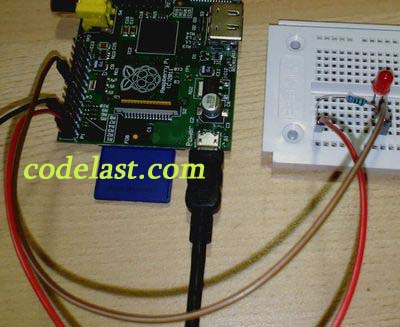
首先,你当然要购买一些发光二极管,电阻,导线,面包板之类的必需电子元器件。看一下我接好线的实物图:
First of all you should buy some essential electronic components such as LEDs, resistor, wires, bread board, etc. Let's have a look at the state of wiring done:
【3】关于GPIO / About the GPIO
GPIO是通用输入输出(General Purpose Input Output)的简称,可以通过软件控制芯片上的GPIO口来定义它是输出还是输出接口。
GPIO接口没有定义特殊的功能,并且通常是不使用的。之所以有GPIO,是因为系统有时需要一些额外的控制线路以便于提供一些额外的功能。
From Wikipedia:
General Purpose Input/Output (GPIO) is a generic pin on a chip whose behavior (including whether it is an input or output pin) can be controlled (programmed) through software.
GPIO pins have no special purpose defined, and go unused by default. The idea is that sometimes the system integrator building a full system that uses the chip might find it useful to have a handful of additional digital control lines, and having these available from the chip can save the hassle of having to arrange additional circuitry to provide them.
Raspberry Pi上的GPIO接口在哪里?它是怎么定义的?我在网上找到这样两幅图:
How are the GPIO pins defined in Raspberry Pi? I found two images on the Internet:
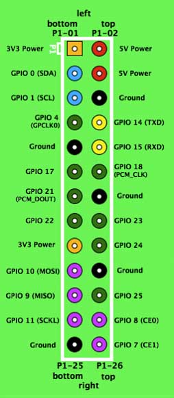
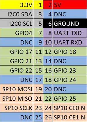
以及另外一幅稍有不同的图:
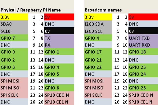
特别要注意的是:尽管你在网上找到的大多数是类似上面两幅图的接口分布图,但是树莓派的GPIO口有两种不同的命名方式,最后这幅图就提供了一个对比。
You should pay special attention to that although most of what you found in the Internet are the pinouts like the first two images, it actually exists two kinds of names and the last image provides a comparison to them.
文章来源:http://www.codelast.com/
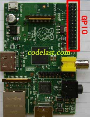
然后我们再来看看Pi上的接口实物图(红框中):
Then we check the real photo of Pi's GPIO(the red box):
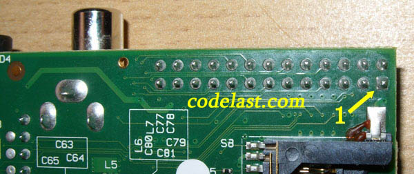
但是,这有一个问题:我怎么知道上面两幅图对应的方向是一致的?也就是说,我如何确定哪个针脚是1,哪个针脚是2,等等?我请教了一个做嵌入式开发的朋友,他告诉我,将Pi的电路板翻到反面,在26个针脚中,焊点为方形的那个针脚就是“1”,在它旁边同一排(两个针脚一排)的那一个就是“2”,依此类推。
But, there is a problem here: how can I know the sequence of the pins? That is, which one is 1, and which one is 2, etc. I ask a engineer friend of mine and he told me a method to identify the sequence of the pins: on the reverse side of Pi's circuit board, check which weld point of the 26 pins has a square shape, and the one who has is just pin "1", and the one next to it in the same row(each row has 2 pins) is pin "2", and so forth.
文章来源:http://www.codelast.com/
在此,我特意拍摄了一张反面焊点的图来说明:
To illustrate that I took a photo for the circuit board:
文章来源:http://www.codelast.com/
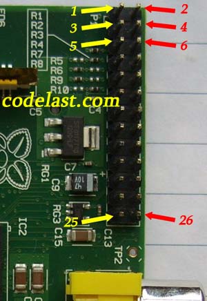
根据这个判断,我得到了Pi的GPIO接口顺序图:
According to the judgement I got the sequence of the ports:
文章来源:http://www.codelast.com/
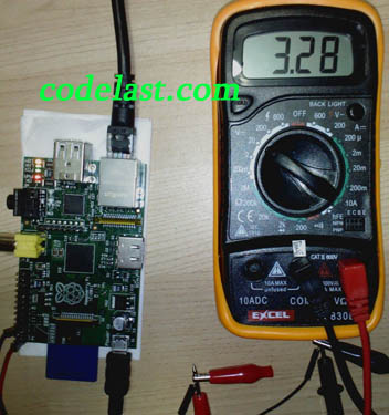
同时,为了保险,还需要用万用表测量一下我们的判断对不对:在Raspberry Pi的工作状态下,将万用表的“+”接到“1”口上,万用表的“-”接到“6”口上,在看看万用表的显示是不是大约为正3.3V,如果不是,那么说明我们弄错了针脚顺序,需要回头再检查!
And for safty reason we should use a multimeter to have a test: turn Pi's power on, and connect the "+" of the multimeter to the "1"(3.3V) we consider is, "-" to the "6"(GROUND) we consider is, then the multimeter should display a approximate +3.3V. If it's not, then we made a wrong judgement on the pin sequence and should go back to check again!
下图是我在树莓派的工作状态下,用万用表测量的实物图:
Below is the photo of using a multimeter to measure the voltage of two pins when Pi is power on:
顺便说一句,Youtube上有一个关于GPIO的视频教程,看完它你会觉得非常有帮助。
By the way, there is a very helpful tutorial on using GPIO on Youtube, you can have a look.
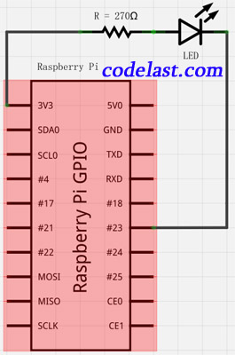
在确认了接口序号无误后,我们就可以开始接线了。在这里,我随意选了一个GPIO口——GPIO 23(即端口16)来接LED。电路图如下:
After be sure with the sequence of the ports, we can start to connect all the electronic components together. I chose the GPIO 23(namely port 16) to connect to the LED and the circuit diagram is as follows:
文章来源:http://www.codelast.com/
就算是这么简单的一个电路,像我一样忘了曾经学过的模拟电路知识的人也会问一句:树莓派的输出电流可以驱动得了发光二极管吗?首先,我在这个链接查到树莓派的3.3V输出口可以提供的最大电流是50mA,并且从这个链接我知道不应让树莓派的单针脚的输出电流>10mA,然后我又查到发光二极管的驱动电流一般是5~20mA。因此,驱动发光二极管是不成问题的。在电流为10mA时,可计算得电阻应为3.3V/0.01A=330Ω,考虑到工作状态下的发光二极管的正向电阻一般为几十到几百欧姆,因此我们拿发光二极管串联一个270Ω的电阻就差不多了。
Even it's such a simple circuit diagram, people who have given their analog circuit knowledge back to their teacher like me may ask that whether the output current of Pi can drive the LED, so I made some investigation... First, from this link I know that the 3.3V pin can output a max 50mA current, and from this link I realize that we should limit the output current of each pin to less than 10mA. Second, I get the info that the current to drive a LED is about 5~20mA, so the current provided by Pi is enough to drive it. Suppose the current is 10mA, we can calculate that the resistance is 3.3V/0.01A=330Ω, and consider that the forward resistance of a working LED is about a few tens of to hundreds of ohms, it's appropriate to connect a 270Ω resistance in series.
补充一句,我使用了一个非常好用的开源软件来画上面的电路图:Fritzing。感谢开源世界的开发者们!
By the way, I used Fritzing(an excellent open-source software) to draw the above circuit diagram and thank for the contribution of the developers!
那么按照我们的猜测,在接好线的情况下,只要我们用软件控制GPIO 23输出高/低电平,就可以让发光二级管闪烁了,那么,软件如何编写呢?
After the wiring is done, it seems that as long as we use a program to control GPIO 23 to output high/low level, we'll make the LED blink. So how to write such a program?
文章来源:http://www.codelast.com/
【4】编写控制GPIO的程序 / Write a program to control GPIO
我使用C来写这个程序。在这里要非常感谢 @drogon 为树莓派的用户提供了一个非常好用的库:WiringPi。通过这个库,我们可以很容易地控制GPIO。
I decide to use C to write the program. Thanks to @drogon that he provide all the Pi users a very good library: WiringPi, and by using the lib we can easily control the GPIO.
WiringPi的安装方法:
Follow these steps to install WiringPi:
①首先确保你已经安装了make,如果没装,很简单:
Be sure to have [make] command installed on your system, if it doesn't, just install it by using:
pacman -S make
②下载安装包,解压,编译,安装:
Download the installation package, unpack, compile & install:
mkdir temp
cd temp
wget http://project-downloads.drogon.net/files/wiringPi.tgz
tar xf wiringPi.tgz
cd wiringPi/wiringPi/
make
make install
这样就算安装完了。
So the installation is done.
③下面写程序测试:
Then write a test program:
// led.c

#include <wiringPi.h>
#include <stdio.h>
#include <stdlib.h>

int main (int argc,char* argv[])
{
	if (argc < 2) {
		printf("Usage example: ./led 4 \n");
		return 1;
	}
	int pinNumber = atoi(argv[1]);

	if (-1 == wiringPiSetup()) {
		printf("Setup wiringPi failed!");
		return 1;
	}

	pinMode(pinNumber, OUTPUT); // set mode to output
	while(1) {
	  digitalWrite(pinNumber, 1); // output a high level
	  delay(800);
	  digitalWrite(pinNumber, 0); // output a low level
	  delay(800);
	}

	return 0;
}
需要注意的是,一旦你用digitalWrite()函数置了高电平,那么只要你不把它置为低电平,它将一直维持在高电平。
Note that once you use function digitalWrite() to set a pin to high level, as long as you don't set it to low level, it will be kept in high level all the time.
编译程序:
Compile the code:
gcc led.c -o led -lwiringPi
文章来源:http://www.codelast.com/
运行程序:
Run the program:
./led 4
可以看到LED开始闪烁了(如下面的Youku视频所示)。这里向程序传入了一个参数4,它代表你要置高电平的是GPIO几。为什么是4呢?因为上面已经说了,树莓派的GPIO口有两种命名方式,一种是树莓派的方式,另一种是Broadcom的方式,当使用WiringPi时,应参考前者,因此,对应到Broadcom方式的GPIO 23上,那就应该是GPIO 4,所以应该向程序输入参数4。
Will see that the LED start to blink shown as this Youtube video. Here we give an argument 4 to the program and it represents the GPIO number which you want to set to high level. Why it's 4? We've said that Pi has two kinds of GPIO pinout names, one is Raspberry Pi, another is Broadcom. When using WiringPi library we should refer to the first one so it is GPIO 4 to correspond to the GPIO 23 of Broadcom way. So we must use 4 as the argument.
至此,本文的主要目的已经达到。如果你还想对树莓派了解更多,请看这些文章。
So the main purpose of this article has been reached. If you want to know more about Pi, please read these articles.
文章来源:https://www.codelast.com/
➤➤ 版权声明 ➤➤
转载需注明出处:codelast.com
感谢关注我的微信公众号(微信扫一扫):

make install 的时候
install: cannot change permissions of `/usr/local/lib': Operation not permitted
Makefile:83: recipe for target 'install' failed
make: *** [install] Error 1
这个样子了QAQ
求救。
有root权限吗?安装了sudo程序吗(安装脚本中可能使用了)?
另外,最新版的WiringPi已经不是文章中所写的那样安装了,请阅读WiringPi自带的README.TXT文件
hi, 执行 gcc led.c -o led -lwiringPi 时报错了:
led.c:l:22:fatal error:wringPi.h:No such file or directory.Compilation terminated.谢谢
参考文中第【4】节
hi, 执行 gcc led.c -o led -lwiringPi 时报错了,
/usr/lib/gcc/arm-linux-gnueabihf/4.6/../../../libwiringPi.so: undefined reference to `i2c_smbus_write_byte'
/usr/lib/gcc/arm-linux-gnueabihf/4.6/../../../libwiringPi.so: undefined reference to `i2c_smbus_read_byte'
/usr/lib/gcc/arm-linux-gnueabihf/4.6/../../../libwiringPi.so: undefined reference to `i2c_smbus_write_byte_data'
/usr/lib/gcc/arm-linux-gnueabihf/4.6/../../../libwiringPi.so: undefined reference to `i2c_smbus_write_word_data'
/usr/lib/gcc/arm-linux-gnueabihf/4.6/../../../libwiringPi.so: undefined reference to `i2c_smbus_read_word_data'
/usr/lib/gcc/arm-linux-gnueabihf/4.6/../../../libwiringPi.so: undefined reference to `i2c_smbus_read_byte_data'
collect2: ld returned 1 exit status
不知道是为什么呢
尝试安装 libi2c-dev库,参考:
http://www.raspberrypi.org/forums/viewtopic.php?f=31&t=19680
谢谢,弄好了
这个c语言的代码要写在哪里?
在树莓派上编译这段C程序并运行
请问要怎么用GPIO来实现触发遥控器的按钮?
不是吧,什么系统下运行的?我想知道这个库的实现方式,应该是通过驱动程序的
楼主,你原理图画错了~~~~~~~bcm gpio应该是第8个口哦~~~不是第6个哦。
+1
hi ,看了你的代码受益匪浅,不过感觉下面 argc 判断是不是应该 <2 才对 :)
if (argc < 1) {
printf("Usage example: ./led 4 \n");
return 1;
}
笔误,感谢指出。已修改。